產(chǎn)品描述
·Product Overview
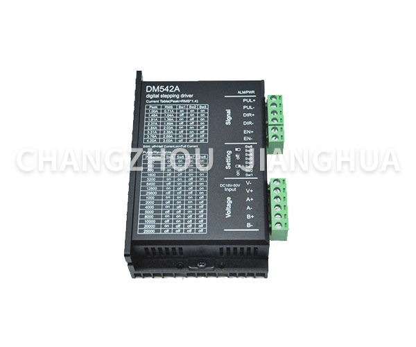
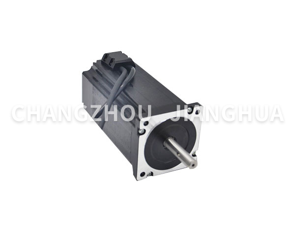
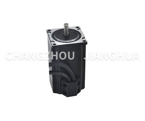
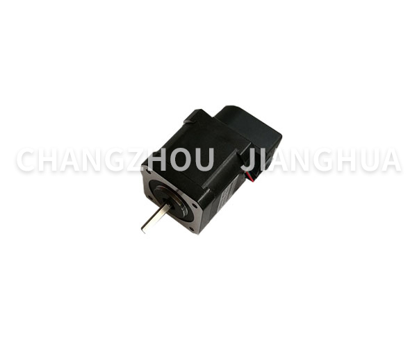
DM542A driver has lower motor heating, running noise, higher stability and lower cost than M542 driver. It mainly drives 42 and 57 two-phase hybrid stepping motors. There are 15 microsteps, and the number of steps is 25000 Pulse/rev; The operating peak current range is 1A - 4.2A, the output current has 8 grades, and the current resolution is about 0.45A; It has automatic half current, over-voltage and over-current protection functions. The driver is DC powered. The recommended working voltage range is 24VDC - 36VDC. The voltage shall not exceed 50VDC and not be lower than 20VDC.
·Features
● Intelligent current control, improve dynamic Q value, greatly reduce motor heating
● Anti resonance technology can easily break through the medium speed resonance zone, with good characteristics of medium and high speed.
● The improved PWM control algorithm makes the motor and driver generate less heat.
● No obvious noise and vibration when switching from full flow to half flow.
● Capable of driving 4, 6 and 8 wire two-phase stepping motor
● Optical isolation differential signal input
● Pulse response frequency can reach 200KHz
● Convenient current setting
● It has overvoltage, undervoltage, short circuit and other protection functions
·Main application fields
Suitable for all kinds of small and medium-sized automatic equipment and instruments, such as engraving machines, marking machines, cutting machines, laser processing, CNC machine tools, automatic assembly equipment, etc. The utility model has the advantages of low cost, low noise and high speed.
Driver Function Description
Drive function
Operating Instructions
Microstep number setting
The driver microstep number is set by four SW5-SW8 dial switches, which have 15 microstep numbers in total. When the user sets the micro step subdivision, the driver should be stopped first. Please refer to the layout of the driver for detailed microstep number settings.
Output current setting
The output current of the driver is set by the three dial switches SW1-SW3. The output current has 8 levels. For specific output current settings, please refer to the layout of the driver.
Automatic half flow function
The user can set the automatic half flow function of the driver through SW4. Off indicates that the static current is set to half of the dynamic current, and on indicates that the static current is the same as the dynamic current. In general use, SW4 should be set as off to reduce the heating of motor and driver and improve the reliability. About 0.4 seconds after the pulse train stops, the current automatically reduces to about half (60% of the actual value), and the calorific value theoretically reduces to 36%.
Signal interface
PUL + and PUL - are the positive and negative ends of the control pulse signal; DIR + and DIR - are positive and negative terminals of direction signal; ENA + and ENA - positive and negative terminals of enable signal.
Motor interface
A + and A - connected to the positive and negative ends of phase A winding of stepping motor; B+and B - connected to the positive and negative ends of phase B winding of stepping motor. When A and B windings are exchanged, the motor direction can be reversed.
Power interface
DC power supply is adopted, the recommended working voltage range is 20-40VDC, and the power supply power is greater than 100W.
indicator light
The drive has two red and green indicators. The green light is the power indicator, which is always on when the driver is powered on; The red lamp is a fault indicator lamp. When overvoltage and overcurrent faults occur, the fault lamp is always on. After the fault is cleared, the red light is off. When the drive fails, the fault can be cleared only by re powering on and re enabling.
Installation Instructions
The overall dimensions of the drive are: 118 × seventy-five point five × 34mm, and the installation hole spacing is 112mmmm. Both horizontal and vertical installation can be adopted, and vertical installation is recommended. During installation, it shall be closely attached to the metal cabinet to facilitate heat dissipation.
Parameter setting
DM542 driver adopts 8-bit dial switch to set subdivision precision, dynamic current and half current/full current. The detailed description is as follows:

Working current setting
Output current | Reference current | SW1 | SW2 | SW3 |
1.00A | 0.71A | on | on | on |
1.46A | 1.04A | off | on | on |
1.91A | 1.36A | on | off | on |
2.37A | 1.69A | off | off | on |
2.84A | 2.03A | on | on | off |
3.31A | 2.36A | off | on | off |
3.76A | 2.69A | on | off | off |
4.20A | 3.00A | off | off | off |
Microstep tessellation settings
Steps/revolution | SW5 | SW6 | SW7 | SW8 |
400 | off | on | on | on |
800 | on | off | on | on |
1600 | off | off | on | on |
3200 | on | on | off | on |
6400 | off | on | off | on |
12800 | on | off | off | on |
25600 | off | off | off | on |
1000 | on | on | on | off |
2000 | off | on | on | off |
4000 | on | off | on | off |
5000 | off | off | on | off |
8000 | on | on | off | off |
10000 | off | on | off | off |
20000 | on | off | off | off |
25000 | off | off | off | off |
Installation dimensions


